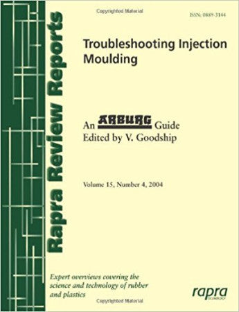
Troubleshooting Injection Moulding
Injection moulding is one of the most commonly used processing technologies for plastics materials. Proper machine set up, part and mould design, and material selection can lead to high-quality production. This review outlines common factors to check when preparing for injection mould components so that costly mistakes can be avoided. Sometimes problems occur in producing parts of the desired quality and there are visible surface defects. Due to the complex interrelationship between the part and the mould, the moulding compound, and the processing, it is often hard to recognise the source of the problem to remedy it. Defects can be classified into: sink marks, streaks, gloss differences, visible weld lines, jetting, diesel effect (burns), record grooves effect, stress whitening or cracking, incompletely filled parts, flash, visible ejector marks, deformation during demoulding, flaking of the surface, cold slugs or cold flow lines, entrapped air and blister formation, dark spots, and dull spots near the sprue.
This review examines the different types of surface defects that can be identified in plastics parts and looks at ways of solving these problems. Useful flow charts to illustrate possible ways forward are included. Case studies and a large number of figures make this a very useful report.
This review examines the different types of surface defects that can be identified in plastics parts and looks at ways of solving these problems. Useful flow charts to illustrate possible ways forward are included. Case studies and a large number of figures make this a very useful report.
1. Introduction
1.1 Optimising the Moulding Part
2. Detection, Classification and Troubleshooting Defects
2.1 Classification
2.2 Flow Charts for Troubleshooting
2.3 Sink Marks
2.3.1 Physical Cause
2.3.2 Correcting Sink Marks
2.4 Streaks
2.4.1 Burnt Streaks (Brown or Silver)
2.4.2 Moisture Streaks
2.4.3 Colour Streaks
2.4.4 Air Streaks/Air Hooks
2.4.5 Glass Fibre Streaks
2.5 Gloss/Gloss Differences
2.5.1 Physical Cause
2.5.2 Correcting Gloss/Gloss Differences
2.6 Weld Line (Visible Notch or Colour Change)
2.6.1 Physical Cause
2.6.2 Improving a Weld Line (Visible Notch or Colour Change)
2.7 Jetting
2.7.1 Physical Cause
2.7.2 Correcting Jetting
2.8 Diesel Effect (Burns)
2.8.1 Physical Cause
2.8.2 Correcting Diesel Effect (Burns)
2.9 Record Grooves Effect
2.9.1 Physical Cause
2.9.2 Correcting Record Grooves Effect
2.10 Stress Whitening/Stress Cracks
2.10.1 Physical Cause
2.10.2 Correcting Stress Whitening/Stress Cracks
2.11 Incompletely Filled Parts
2.11.1 Physical Cause
2.11.2 Correcting Incompletely Filled Parts
2.12 Oversprayed Parts (Flashes)
2.12.1 Physical Cause
2.12.2 Correcting Oversprayed Parts (Flashes)
2.13 Visible Ejector Marks
2.13.1 Physical Cause
2.13.2 Correcting Visible Ejector Marks
2.14 Deformation During Demoulding
2.14.1 Physical Cause
2.14.2 Correcting Deformation During Demoulding
2.15 Flaking of the Surface Layer
2.15.1 Physical Cause
2.15.2 Correcting Flaking of the Surface Layer
2.16 Cold Slugs/Cold Flow Lines
2.16.1 Physical Cause
2.16.2 Correcting Cold Slug/Cold Flow Lines
2.17 Entrapped Air (Blister Formation)
2.17.1 Physical Cause
2.17.2 Correcting Entrapped Air (Blister Formation)
2.18 Dark Spots
2.18.1 Physical Cause
2.18.2 Correcting Dark Spots
2.19 Dull Spots Near the Sprue
2.19.1 Physical Cause
2.19.2 Correcting Dull Spots Near the Sprue
3. Case Studies of Injection Moulded Components
3.1 Threaded Connecting Sleeves for Ink Drafting Apparatus
3.2 Meter Cases
3.3 Wristwatch Glass
3.4 Alarm Clock Glass
3.5 Glass Cover for Digital Gauge
3.6 Plug Boards with Insert Pins
4. Effects of Injection Moulding Parameters
4.1 Internal Mould Temperature and Pressure
4.2 Relationship of Injection and Mould Cavity Pressures
4.3 Injection Pressure and Injection Time
4.4 Filling Speed
4.5 Filling Speed and Orientation
4.6 Effects of Too High Filling Speed
5. Machine Specifications
5.1 Clamp Force
5.2 Injection Unit
5.3 Feeding Hopper
5.4 Barrel Residence Time
5.5 Precompression of the Melt
5.6 Check Valve
5.7 The Nozzle
5.8 The Feed System
5.9 The Mould Temperature
5.10 The Importance of Adequate Venting
5.11 Multi-Cavity Moulds
General Information on Wear and Tear
6. Conclusion
Abbreviations and Acronyms
Abstracts from the Polymer Library Database
Subject Index
Company Index
The editor, Dr. Vannessa Goodship, is a Senior Research Fellow with 15 years
experience in industry and expertise in injection moulding technology. She
is based at the Warwick Manufacturing Group in the Advanced Technology
Centre at the University of Warwick.
experience in industry and expertise in injection moulding technology. She
is based at the Warwick Manufacturing Group in the Advanced Technology
Centre at the University of Warwick.


